Tube Reactor Conclusions
Temperature control
Steady state: Radial uniformity is almost automatic, except for the first and last few wafers in the load. Axial uniformity is achieved using multi-zone heaters. Quartz hardware allows operation at temperatures in excess of 1000°C, although at very high temperatures migration of sodium through the furnace tube becomes a concern for MOS device fabrication.
Transient temperature control is much more challenging. Wafers must be loaded slowly, or system temperature ramps used; tens of minutes are required to reach stable temperatures. Modern reactors employ model-based temperature control to minimize heatup and cooldown ramp times.
Radial film uniformity
Radial uniformity is excellent if pressure is low and surface reaction rate slow. The powerful influence of total pressure explains the prevalence of LPCVD tube applications.
Axial film uniformity
Wide variations can occur depending on loading conditions, operating temperature, gas flow rates, and injection scheme.
Productivity advantages
It is easy to achieve large wafers/load by operating at low pressure to allow close wafer spacing: 100 wafers may be processed in a single batch.
Productivity disadvantages
Low rates required to maintain uniformity, and slow thermal response, imply long process times. Large batch sizes necessary to achieve reasonable throughput put a large number of wafers at risk in each run should a problem occur. The complex cantilever supports, specialized wafer boats, and possibly also cages, are expensive and require periodic cleaning.
Process advantages
Very high purity quartzware can be fabricated; high temperature operation with minimal metallic contamination of films is straightforward in this type of reactor.
Process disadvantages
It is very difficult to implement plasma reactors in tube configuration.
Tube reactors are commonly employed for "front-end" IC fabrication steps: polysilicon deposition, silicon nitride deposition, and high-temperature silicon dioxide deposition from TEOS, as well as deposition of doped oxides such as BPSG or PSG. This type of reactor is not normally employed for deposition of metals such as tungsten, copper, or TiN due to problems in cleaning.
"Back-end" processes (after metal deposition) require lower temperatures and often employ plasma techniques. Some plasma tube reactors were developed in the early 80's but difficulties with uniformity and maintenance have eliminated this approach in favor of showerhead and high-density plasma approaches, often in single-wafer configurations.
Reactor Practicalities: Sideways or Upwards?
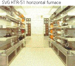
Modern commercial reactors come in two flavors: horizontal and vertical. Horizontal reactors are the original version and have been around for decades. A representative commercial tool is shown below. The photograph depicts two banks of furnaces, each of which stacks three large tubes one atop the other.
One of the key problems with any real reactor is how to get wafers in and out. In R&D facilities or in times before the dawn of humanity (that is, when the author was young) one could use a quartz "push rod" to simply shove a quartz boat full of wafers along the bottom of the tube. However, this generates a LOT of dust as the boat scrapes along.
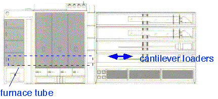
In the horizontal tube reactor, the indsutrial solution is to use a cantilever* loader: a long paddle, supported at one end, holding the quartz fixturing onto which wafers are placed. The paddle is generally made of something refractory like silicon carbide; quartz will slowly sag and is less frequently employed. The cantilever loader allows one to load a large number of wafers onto the quartz fixture, and then insert them smoothly into the furnace without scraping the tube and generating particles.
Cantilever loaders present several challenges. The fundamental one is that they make the furnace + loader huge: at least twice the length of the tube, as shown schematically below. The combined loader + furnace assembly might be 10 feet (3 meters) deep, and all the loader needs to be inside expensive cleanroom space.
It is also mechanically difficult to make a clamp which can support the considerably torque placed on the paddle, while still allowing the precise adjustment required to center the cantilever within the tube and avoid scraping at any point during the load.
In many fabs and applications, horizontal furnaces have been replaced by vertical furnaces. These turn the tube vertically upward and load from below. An example is shown below.
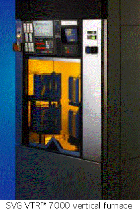
Vertical furnaces lend themselves to conventional wafer automation approaches: the wafers can be loaded in one or more cassettes with the wafers horizontally positioned within the cassette, and then a robot arm can pick up each wafer and load it into the quartz boat without needing to change the wafer orientation. The boat is indexed vertically for each slot. Multiple tubes can be loaded with one robot; a cooling station can be provided to improve throughput.
Vertical furnaces also use less cleanroom square footage: they consume space vertically, where it is typically available. I suspect that vertical furnaces also benefit from better convection behavior: natural convection in the region around a conventional horizontal tube furnace will tend to cool the sidewalls of the tube relative to the top and bottom, ruining the nice radial symmetry of the system, whereas a vertical furnace will simply suffer some gradients along the tube, easily remedied with segmented heaters. However, I have no data to support this statement. I have also been told that vertical furnaces have better particle control; this is unsurprising, since any particles big enough to be affected by gravity will tend to fall on the first wafer (which can be a dummy) and spare the rest.
Contamination control is always an issue with furnace processing. Contamination can be monitored using SIMS, total x-ray reflection (TXRF), or lifetime measurements. Commercial equipment exists which provides rapid non-contact lifetime maps, an excellent method of detecting heavy metals such as iron in normal fab operations.
Alkali metals migrate readily in silicon dioxide, typically as positive ions, and thus will lead to threshold voltage instability. Trace contamination from resist residues or etch reactors will contaminate a whole furnace load in a subsequent high-temperature step. Certain oxidation and anneal processes early in the front-end (field oxidations, trench fill, and power-device processes) may be performed at temperatures as high as 1150-1200 °C. At these high temperatures, contamination from the furnace itself, particularly iron from SiC parts, can be significant.
However, over the years contamination in the front end has become less of an issue: modern fabs use fewer high-temperature steps, and contamination from etch processes and photoresist has been significantly reduced. Use of an electric field to control contamination has been demonstrated ["Applying an electric field to control metals in furnaces", D. Dobkin, I. Rapoport, V. Starov, Y. Raskin and S. Zaidman, Solid State Technology Aug 2000] but may not be necessary if good procedures are followed and modern equipment employed.
*which is an excuse to introduce my only mechanical engineering joke:
Q: What did the stone beam say to the column?
A: If a rock can do it, why can’t a lever?
Return to Tutorial Table of Contents
Book version of the CVD Tutorial