Capacitive Plasmas
The Low-Pressure, Cold-Plasma State
The most commonly encountered plasma in CVD applications is the capacitive or "RF diode" plasma. A simplified view of such a reactor might look like this:
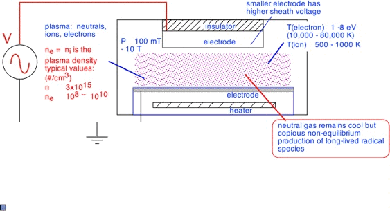
The plasma is excited and sustained by applying a voltage --typically AC or RF, 60 Hz to many MHz -- between the two electrodes. The "capacitive" moniker arises from the nature of the coupling to the plasma. The plasma forms sheaths, regions of very low electron density, at solid surfaces: the RF voltage appears mostly across these sheaths as if they were the dielectric region of a capacitor, with the electrode and the plasma forming the two plates.
The system pressure is typically between about 100 mTorr and 10 Torr. The electrodes are typically cylindrical, with the separation between the two electrodes usually small compared to the electrode diameter. The electrode "gap" is an important parameter; it varies from about 0.5 cm to 10 cm, generally getting smaller for higher pressure operation. Typical gaps are a few hundred times the mean free path, so electrons undergo many collisions but do not have time to transfer their energy to the neutral gas. However, practical limitations on chamber size generally lead to increasing ratios, and "hotter" plasmas, at higher pressures. Some representative values, with length in millimeters:
Pressure Mean Free Path Gap Gap/MFP 100 mT 0.5 50 100 1 Torr 0.05 20 400 10 Torr 0.005 5 1000
We have for simplicity used values for nitrogen molecules here. In fact, the mean free path for electrons is longer and has a rather complex dependence on electron energy.
In practice, typical electron temperatures are around 5 eV. Electron temperature varies weakly with other parameters: it is dominated by the requirement that the electrons provide enough ions to keep the plasma going.
Plasma Density
The ion density is equal to the electron density in the plasma, to ensure overall balance of charge: the density of electrons and ions is just known as the plasma density. [This is true for electropositive plasmas, in which the only significant ions are positive. Electronegative plasmas result when attachment of electrons to form negative ions is important; such plasmas have very different properties. They are particularly important in etching applications, but less frequently encountered in deposition.] About 100 eV is required to produce an ion in a typical low-pressure plasma, when all the losses due to collisions, excitation/de-excitation, and inefficient energy transfer are accounted for. The ions are mainly lost by diffusion to the walls in a low-pressure plasma. The ion density is set by the balance between the input power, which heats the electrons and provides energy to ionize, and the loss of ions to the walls.
Plasma density in typical capacitive plasmas is very "low": the fractional ionization is only about 0.01% (1 molecule in 10,000 is ionized). Fractional excitation can be much higher, since excitation and dissociation usually require less energy than ionization. The electrons are distributed in a vaguely Maxwellian fashion, as exp(-E/kTe); thus there are many more electrons with energies of e.g. 8 or 10 eV, able to dissociate, than there are at 16-25 eV driving ionization processes.
substance dissociation energy (eV) ionization energy (eV) H2 4.5 15.4 O2 5.2 12 CH4 4.5 12.6 F2 1.6 15.7
Sheath Formation
As noted above, electropositive plasmas form sheaths of low electron density -- also known as dark spaces from their visual appearance -- near solid surfaces. At right we show the plasma in a potential diagram, similar to an energy band diagram for a semiconductor device. Ions roll "down hill" in the sheath regions, acquiring energy which is dissipated when the strike the walls. Electrons float bubble-like upwards, and are thus confined by the potential away from the sheath regions, which therefore have few electrons. Occasionally an ion striking the wall surface knocks off an electron -- a secondary -- which then is accelerated into the plasma by the sheath electric field.
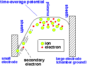
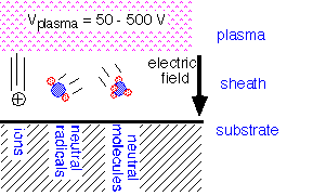
An electrically isolated object in the plasma will have a sheath around it, since the mobile electrons are lost more readily by diffusion to the surface, giving the plasma a net positive charge until a sheath forms to ensure charge balance. Such sheaths have a potential of typically 10-25 volts. The sheath potential in a capacitive plasma is much larger: it varies during the RF cycle, with peak values of several hundred volts often present.
In consequence, the substrate surface in a plasma is likely to be bombarded with ions, whose kinetic energy varies from a few 10's to several hundred eV, along with the usual flux of neutral molecules, and lots of neutral but reactive radicals.
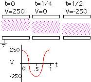
The actual potential across the sheaths varies with time in order to add up to the applied RF voltage (very little voltage typically appears across the plasma itself). The plasma is always more positive than either of the electrodes, as otherwise electrons would rapidly escape from the plasma. Thus one sheath grows and the other sheath shrinks as we proceed through the RF cycle. At t=0 in the example below, the top electrode has a "floating" sheath with only a few volts across it, allowing electron current to flow (to neutralize the ions that struck the surface during the remainder of the cycle), while the bottom electrode has a sheath with e.g. 240 V potential drop, causing energetic ion bombardment of the surface. A half cycle later (t=1/2) the sheath on the bottom electrode is small, and that on the top electrode is large.
Return to Tutorial Table of Contents
Book version of the CVD Tutorial