Intercepting a tag reply
Daniel M. Dobkin
update August 2021
As pointed out in our discussion of link budgets, a UHF tag IC has only a few tens of microwatts available if it is to have a range of more than 5 meters. This is not enough power to support sophisticated encryption or authentication. ISO 18000-6C (EPC Class 1 Generation 2) uses 32-bit passwords to control memory lock states and tag kill operations. Writing these passwords is protected by a cover code operation, in which the tag sends a random number and the reader adds that random number bitwise modulo 2 to the data it wishes to send. Cover coding is secure if the tag signal can't be intercepted and the random number is not re-used. The tag backscattered power is much smaller than the reader transmitted power -- around 0 to -20 dBm -- so it is more difficult to intercept and interpret, but it is by no means impossible. In this brief report we describe how a conventional 18000-6C tag response can be intercepted.
Experimental Procedure: Short-Range Tests
The experimental setup is shown in Figure 1. An MPR5000 PC-card-based UHF reader, obtained from WJ Communications before it was purchased by TriQuint and that by Qorvo, was operated under a custom Python interface. A 6 dBi linearly-polarized patch antenna was connected by a short cable to the reader. A standard commercial UHF passive tag was placed between the reader and a simple half-wave wire dipole receiver antenna, initially at a distance of about 1.5 meters (but longer distances were also tested, as described below). The receiver was an MPR reader modified for use as a channel sniffer: the transmitter is disabled and the converted baseband I and Q (in-phase and quadrature) signals are extracted for display on an Agilent digital oscilloscope.
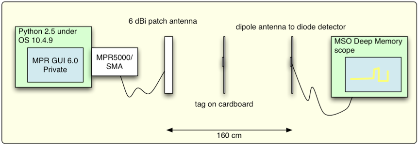
Figure 1: schematic depiction of test setup.
Both readers were run at a fixed radio channel (nominally 920.8 MHz here). This is an important aspect of the test to take note of. A normal commercial UHF reader in the United States is obligated to hop no less often than every 0.4 seconds (see the discussion of RFID frequency bands for more information). If we attempted to perform the same operation on such a radio, using a fixed-channel receiver, we would intercept only one out of every 50 packets. Clearly it is much more convenient for testing purposes to fix the transmit frequency. Note that such operation is technically illegal without a license, though normally permitted for research purposes where reasonable precautions are taken to minimize interference with other unlicensed users (as was the case here).
A photograph of the test setup is shown in Figure 2. The reader antenna and the sniffer antenna are rotated to minimize cross-coupling, to make it easier to see the modulated signal from the tag. In an anechoic environment the two antennas would be cross-polarized (one horizontal, the other vertical); in this case, with lots of junk close to the antennas, the polarization angles were empirically adjusted for minimum coupling.
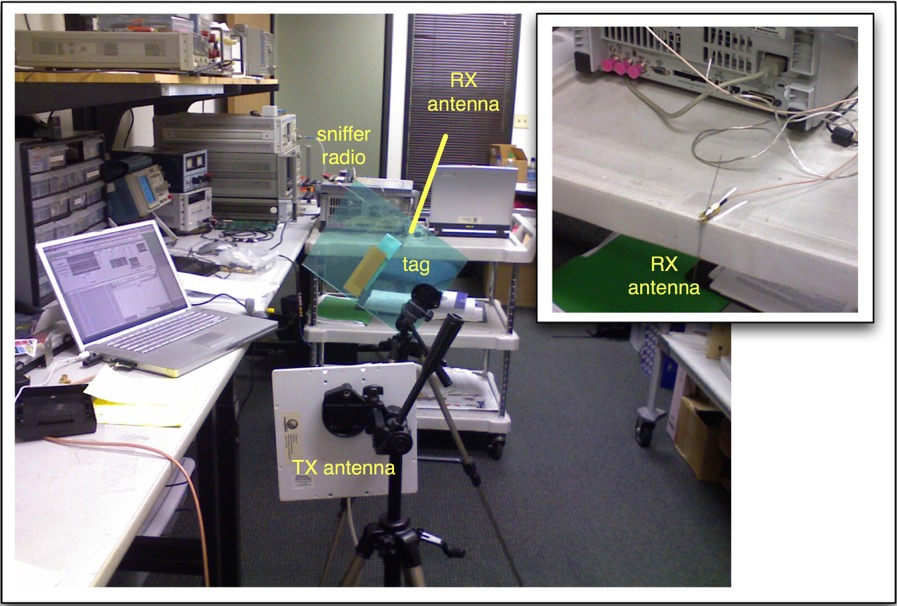
Figure 2: actual test setup.
The inventory setup is shown in Figure 3; the parameters are typical for an 18000-6C (EPC C1G2) tag. The nominal output power of the reader was 25 dBm (about 300 mW). The session is set to 0, so that the tag can be inventoried repeatedly (the Session flag is reset to A after each inventory). The starting value of Q, Qst, is also set to 0, so that the tag can be expected to respond to each inventory attempt. 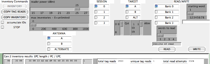
Figure 3: Inventory configuration
Results
A typical example of an intercepted signal is shown in Figure 4. Recall that the reader is sending an amplitude-modulated, pulse-interval-encoded signal, and the tag responds with the FM0 variant of frequency-shift keying. It is very easy to see that we've intercepted both signals.
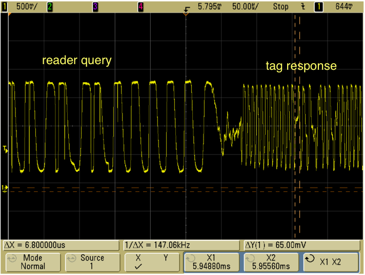
Figure 4: Reader query and tag response.
To demonstrate that the received signal is interpretable, we show a closeup in Figure 5. The tag sends twelve FM0 '0' symbols (the pilot tone), followed by the symbols 1010(v)1, where (v) indicates a violation of the FM0 rules -- in this case, an anomalously long time in a constant state. These features are readily discernible in the displayed signal.
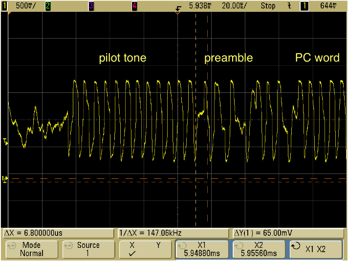
Figure 5: Closeup of tag response to reader query.
The amplitude of the tag signal is observed to vary from time to time; an example is shown in Figure 6, which depicts a complete exchange between a reader and tag (that is, the reader issues a Select command and a Query, the tag responds with a random number RN16, the reader acknowledges the random number, and the tag provides its protocol control word (PC) and unique identifier (EPC). It is apparent that the RN16 from the tag has a small and variable amplitude; the PC+EPC, on the other hand, appears to have a large and constant amplitude.
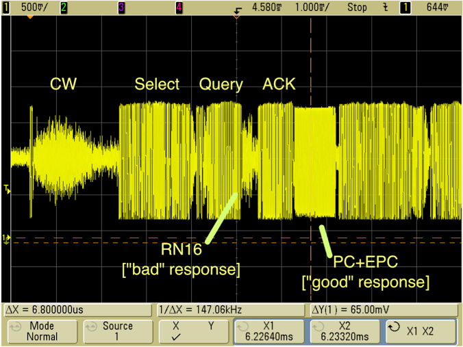
Figure 6: An intercepted inventory exchange.
The origin of this curious behavior becomes apparent in Figure 7, which depicts BOTH the in-phase and quadrature channels. Recall that these are simply the downconverted signals offset by 90 degrees in phase. The I response is reduced in amplitude and somewhat variable, whereas the Q signal has a large and constant amplitude (limited by the sniffer radio's receive chain).
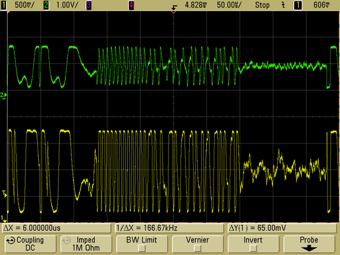
Figure 7: I (green) and Q (yellow) tag responses.
Remember that we are using two completely independent radios, whose local oscillator (LO) signals depend on physically distinct reference crystals. In general, we can expect that the LO frequencies do not exactly agree. Therefore, the relative phase of the reader and sniffer will drift with time. Sometimes the tag scattered signal will be primarily in the I channel of the sniffer, sometimes in the Q channel. If we monitor only one of the channels, we will inevitably encounter spurious zero crossings as the phase of the signal becomes orthogonal to the phase we are monitoring. However, if the full vector received signal is available, it is straightforward to remove this phase drift through either carrier recovery or signal processing.
To verify that the received signal was meaningful, I picked a nice-looking tag response and decoded it by hand:
Pilot tone
Preamble
0011 0000 0000 0000
0011 0000 0000 1000
0011 0011 1011 0010
1101 1101 1101 1001
0000 0001 0100 0000
0011 0101 0000 0101
0000 0000 0000 0000
0100 0010 1110 0111
that is:
30 00 PC word
30 08 33 b2 dd d9 01 40 35 05 00 00 =ID of tag in field
16-bit CRC
So I was able to decode a full PC+EPC without a bit error. To crack the 18000-6C cover code, we need only intercept an RN16, a significantly easier task. Thus, it is clear that a tag signal can be intercepted by a physically-distinct attacker, allowing one to listen in on nominally-secure operations such as writing a password to a tag.
Long-Distance Intercepts
OK, let's face it: an attacker who has to locate their receiver within a meter or two of the reader faces a significant risk of discovery. A user with open eyes should be secure enough. So what about longer distances? In a second set of measurements, the sniffer was popped on a cart and moved to a more remote location past a typical indoor partition wall, as shown in Figure 8.
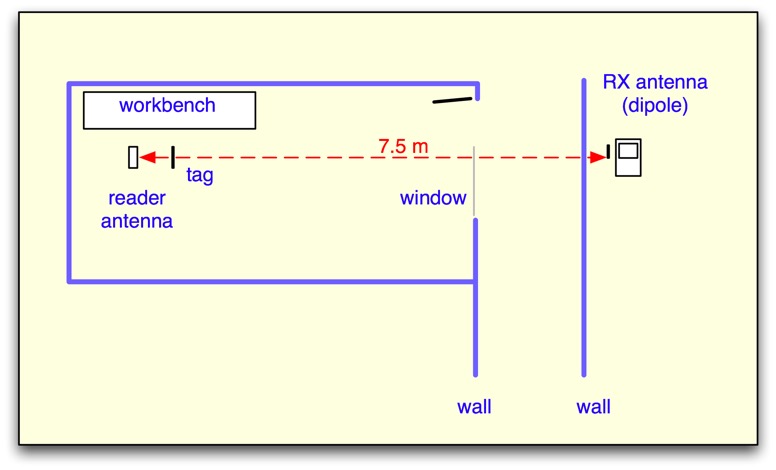
Figure 8: The intercepting antenna was moved to a distance of 7.5 meters from the reader, with an intervening interior partition wall. 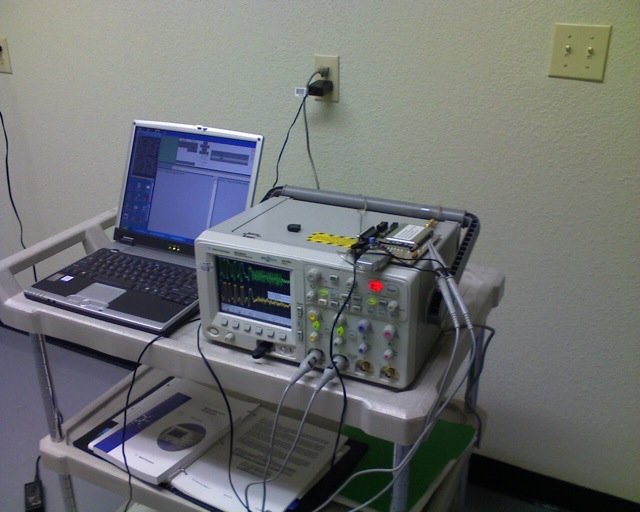
Figure 9: remote setup; the receive dipole antenna is behind the oscilloscope.
The received signal amplitude was significantly reduced, but the signal-to-noise ratio was still large at the remote site (Figure 10). To demonstrate that the signal was still intelligible, a complete tag reply was deciphered manually (Figure 11), with the expected result:
Decode:
Pilot tone
Preamble
0011 0000 0000 0000 30 00
0011 0000 0000 1000 30 08
0011 0011 1011 0010 33 b2
1101 1101 1101 1001 dd d9
0000 0001 0100 0000 01 40
0011 0101 0000 0101 35 05
0000 0000 0000 0000 00 00
(and CRC follows)
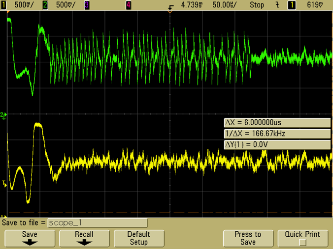
Figure 10: I and Q tag signals for a 16-bit random number from the tag, received at > 7 meters through a wall. 
Figure 11: decoding a full tag signal intercepted at > 7 meters.
We also verified that the signal amplitude is greatly improved if a better sniffer antenna (in this case, a 9 dBi circularly-polarized patch antenna) is used.
Discussion and Conclusions
It is clearly possible to intercept UHF RFID tag backscattered signals, and do so under conditions where the legitimate users might have no visible indication that their work is being intercepted.
How much should this concern RFID users? For most users, interception is a minimal concern: if you are using tags to keep track of boxes that arrive at your dock, anyone who walked by the dock could scan the bar codes or read the tags (if they had a portable reader), and learn more at less cost. The Class 1 Generation 2 standard was mainly designed for these types of applications, and is not meant to be secure against major attacks: if it was, the tags would be much more expensive and have much shorter range!
However, if you are using tags in situations where you are writing data to them that you'd like to keep private -- for example, LOCK or KILL passwords in cases where you really don't want someone else to have them -- you should attend to the physical security of the write operation. Use a smart label printer to write information to the tags, write in a sealed area (with metal or metallic screen walls!), or write in an open area where it is visually possible to ensure that no attackers are within tens of meters of your site.
I'd like to thank John Bellantoni, Nick McCurdy, Joshua Markell, Nathan Iyer and Steven Weigand for assistance with this work.