The RF in RFID: physical layer operation of passive UHF tags and readers
Daniel M. Dobkin
(revised August 2021)
3. RFID Readers
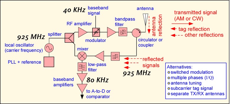
An RFID reader is a specialized radio transmitter and receiver. Like all such devices, the reader must generate signals at the carrier frequency -- around 900 MHz for typical UHF devices -- and modulate this carrier signal to convey information to the tags. It must selectively receive and amplify responses from the tags, and convert the signal from the carrier frequency down to the much lower frequencies characteristic of the information contained in the received signal. A general block diagram of such a radio is depicted below. In the remainder of this discussion we will examine each block.
RFID readers typically operate in unlicensed spectrum. This does not mean their operation is unregulated, but rather that individual devices do not require licenses to operate in a certain band of frequencies, so long as they meet certain requirements. In the US, devices operating in the 902-928 MHz band may operate in one of two fashions: they may hop in a pseudo-random fashion from one frequency channel to the next within the band, or they may use one of several possible broadband digital modulations. Both approaches are intended to reduce interference between neighboring radios. Most RFID readers use the first approach. Thus, the local oscillator and phase-locked loop (PLL) must be able to change from one frequency to another rapidly no less often than every 400 milliseconds. During the frequency hop it is common to turn the transmitter off, to avoid transmitting out-of-band spurious radiation while the synthesizer is trying to lock to the new frequency. It is also possible to put two synthesizers in the radio, so that one is tuning to the next channel while the other transmits, allowing the reader to switch frequencies without the tag losing power, but this adds cost to the reader.
UHF RFID readers face requirements rather different from their more common brethren, such as 802.11 basestations or cellular phone radios. Passive tags are very dumb radios: they have no ability to select among frequencies, and can only detect changes in the amplitude of the transmitted signal -- amplitude modulation (AM). More sophisticated, and spectrally efficient, modulations like phase-shift keying or quadrature amplitude modulation, cannot be used (though EPCglobal Class 1 Gen II defines some modulations that are better than simple AM and yet seen as that by the tag). As a consequence, the transmitter for an RFID reader can be a very simple structure consisting of a synthesizer to produce the transmitted signal, and a variable attenuator, or even a switch, to turn the transmitted signal on and off.
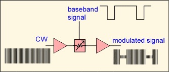
The simple scheme shown has a disadvantage: the abrupt transitions between the ON and OFF states in the digital baseband signal are potentially mapped directly onto the envelope of the transmitted high-frequency signal. Changes in a signal result in increases in its bandwidth; the more abrupt the change, the more spectrum is consumed. Tags are not affected, but increased interference with other collocated readers, or other radios in the vicinity, may result. Generally the baseband signal is smoothed -- filtered -- to make the transitions in state as gradual as possible.
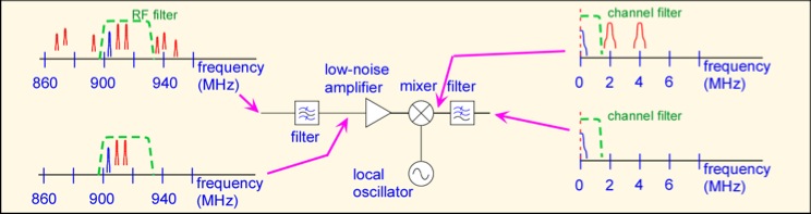
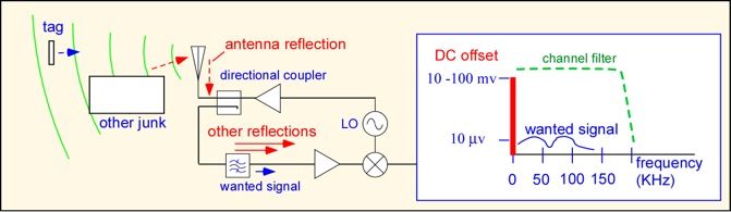
On the receiver side, the frequency reflected from the tag is identical to that being sent by the reader (give or take a bit of Doppler shift). Thus most receivers are homodyne or direct conversion architectures: a bit of the transmitted signal is mixed with the received signal (at the same nominal frequency), so that the carrier frequency is totally removed and only the modulation of the received signal remains. For example, a class 1 tag might reflect the 914-MHz signal from a reader while changing the tag state at around 120 Kbps, leading to a fundamental modulation frequency of 60 KHz. The received (backscattered) signal is mixed with the 914-MHz carrier, producting a 1828 MHz product which is easily filtered out, and a baseband signal centered around 60 KHz, which can be filtered and amplified to recover the information the tag is trying to send. Signals from neighboring readers (hopefully) appear several MHz away, and are easily filtered out at the baseband stage. (It gets harder if the neighboring readers happen to be on next-door neighbor channels to the one you're operating on, or on your frequency.)
[click for animated version]
Design of direct conversion receivers involves some special challenges. The tag signal is not the only reflected signal present; in a single-antenna system there is usually a much larger signal due to unintented reflections from the transmitting antenna. (Even a good antenna has a return loss of about 15 dB, meaning if 1 watt -- 30 dBm -- is transmitted, 15 dBm bounces off the antenna and back towards the reader. This is about 30 mW, vastly more than the -60 dBm (1 nW) or so coming back from a distant tag.) The unwanted reflected signals also mix with the local oscillator signal; since they are not (usually) modulated they produce DC offsets: large DC voltages output from the mixer. Fortunately, if the wanted signal doesn't contain much information near DC -- which will be the case as long as the tag symbols are chosen to ensure frequent transitions in tag state even when the data has long strings of 1's or 0's -- it is straightforward to filter out this offset. A bigger problem is that the offset changes wildly whenever the transmit signal is modulated, as it must be to send information to the tag. The resulting huge swings in the mixer output are harder to filter out, and make it hard to see any reflection from the tag until the receiver has had a few microseconds to recover.
Both of these problems are ameliorated by using separate transmit and receive antennas (a bistatic configuration): in this case instead of the reflected signal from the (single) antenna, the receiver must only deal with the portion of the transmitted signal that sneaks into the receive antenna, typically much smaller than the reflected signal. Isolation of around 40 dB is obtained with the large bistatic antennas commonly used with commercial readers; that's 20-25 dB better than the return loss from a single antenna. However, the use of a pair of antennas adds cost, complexity, and increased space requirements to the reader. One can also use an adaptive antenna tuner or nuller to reduce the reflections from a single (monostatic) antenna, but this solution again involves added expense and complexity.
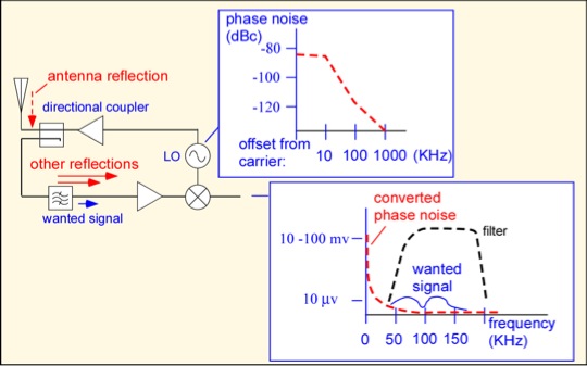
Oscillators don't produce a perfectly pure carrier signal; both the phase and amplitude of the signal can vary. The phase noise can be converted into amplitude noise in the received signal when the large fixed reflection mixes with the local oscillator, if the signal path is not frequency-independent (which it rarely is). Phase noise is normally highest at frequencies very close to the carrier, which are converted to near DC on mixing. To reduce phase noise effects, it helps to use a relatively narrow filter, that passes only the frequencies containing the wanted signal from the tags, and to use the highest tag modulating frequency you can manage, which conflicts with the desire to consume minimal power in tag operation.
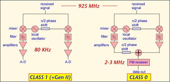
The absolute phase of the reflected signal from the tag is unknown, since the distance to the tag is not controlled. It is therefore necessary to ensure that the signal is received independently of its phase in relation to the local oscillator. A simple approach is to split the local oscillator signal and phase-shift the one branch by 90 degrees. The reflected signal is then mixed with both the in-phase and quadrature (I and Q) signals. No matter what the phase of the received signal, it will produce a signal in either the I or Q branch; in simple terms, if the received signal is a cosine and the I branch is a cosine, the output of the mixer contains a signal like cos2, which when averaged produces a value of 1/2. If the received signal is a sine (90 degrees different in phase), the result of mixing with the I channel is sin*cos, which averages to zero over one or more cycles, but the product of mixing with the Q channel is sin2, which again averages to 1/2. The I and Q channels can be separately digitized and demodulated, or recombined with an additional phase shift to produce an image-reject mixer, which has the virtue that the output is independent of absolute phase (even though for a direct conversion receiver there is no image to reject). An example is shown in the image below at right; such an architecture was used for the old frequency-modulated EPC class 0 tag technology.
Reader Antennas
Large stationary readers used for portals, doors, or conveyor reading usually employ external antennas connected to the reader via a coaxial cable. For 900-MHz passive RFID service these are almost always patch antennas. A patch antenna is composed of a patch of metal -- surprise! -- suspended above a larger ground plane. The typical patch is a square a half-wavelength (about 16 cm) on a side. A patch antenna can be fabricated using metal slices suspended on dielectric spacers, or using lithographic techniques on a circuit board. Patch antennas have typical gain around 6-10 dBi, and a beamwidth of roughly 60-90 degrees. A patch antenna with a symmetric patch and a single feed line will launch a linearly-polarized wave, but several methods are available to create circularly-polarized waves as well. Note that when a circularly polarized transmit antenna is used in a bistatic configuration, a single-dipole tag will backscatter a linearly-polarized wave, but a dual-dipole tag may backscatter a circularly polarized wave. If it does so, the returning wave will be of the opposite sense: that is, if the transmitter is left-hand circular, the backscattered wave is right-hand circular. For this reason, bistatic circularly-polarized antenna pairs are normally of opposite sense.
If you're unfamiliar with the polarization descriptions used above, click on the image below for a quick animated introduction to linearly and circularly polarized radiation. The arrows show the instantaneous direction of the electric field as it moves away from a stylized patch antenna. (To simplify the depiction, the decrease in amplitude of the field as it propagates away from the antenna has been neglected.)
Handheld readers can use reduced-size patch antennas (accomplished by various tricks including use of high-dielectric-constant substrates, cutting slits in the patch to lengthen the path of the currents, and changing the means of feeding the patch), or other structures. Symbol's handheld readers use a very elegant small Yagi-Uda antenna fabricated in copper sheet, that makes very efficient use of space in launching a wave.
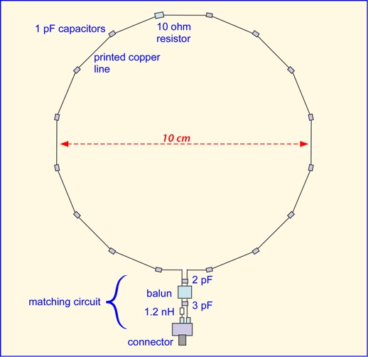
Near-field UHF readers face some special problems. An ideal near-field antenna couples inductively to a nearby loop (the tag antenna) but doesn't radiate. This is a difficult challenge at UHF: the range of an inductive antenna is normally about comparable to the antenna diameter, so to get (say) 5-10 cm of read range one expects to need an antenna 5-10 cm in diameter. However, a simple loop antenna is antiresonant when the perimeter is about 0.4 of a wavelength, which corresponds to a diameter of around 4 cm at UHF frequencies: it will be very difficult to match to a 5-cm loop! A diameter of around 10 cm is series-resonant, and not too hard to match -- but the current distribution on the loop is no longer circular. Instead, the currents accumulate at points around 90 degrees from the feed to make a dipole-like radiation pattern, and there is no magnetic coupling on axis! So a simple loop makes a very poor near-field antenna.
One possible solution is to use a segmented loop. By dividing the loop into small lengths and placing a capacitor between each segment to resonate out the inductance of that segment, the impedance of the antenna remains manageable at any length, and the currents stay roughly in phase around the loop even at series-resonant diameters. One such design (details courtesy of Stephen Weigand and Nathan Iyer) is shown below. Our measurements show that a segmented loop provides 15-20 dB improvement in inductive coupling on axis over a solid loop, and we achieved a read range of around 8 cm on axis using a 10 cm antenna and TI G2 inlays with the dipole removed. Details can be found in our article in Microwave Journal, June, 2007.