| The RF in RFID: physical layer operation of passive UHF tags and readers 4. UHF RFID Protocols Daniel M. Dobkin October 2005; revised April 2007 |
| A communications protocol is a way of organizing the
conversation between devices -- in the case of RFID, between tags and a
reader -- to ensure that information actually gets transferred. A
protocol defines: an air interface: what sort of modulation of the reader signal is used to define a binary one? what's a zero? what kind of signal does the tag send? how fast does everything go? is information sent in discrete packets, and if so how are they formed? medium access control: who gets to talk when? how are collisions between contending users (tags in this context) resolved? data definitions: what sort of data is associated with a tag? what does it mean? Passive RFID tags face some special problems not encountered in most other digital radio systems. Tags are cheap and dumb, so only changes in amplitude of the reader signal can be used; advanced modulations like phase-shift keying or quadrature-amplitude-modulation (QAM) are not available. Further, turning off the power from the reader reduces the power available to the tag, so the modulations of choice for the reader are those in which power is on most of the time; such modulations are wasteful users of spectrum, leading to realtively wide channels or low data rates. The tag reflection can be modulated in phase or amplitude, but the small tag reflection is combined with large reflections from the antenna and ambient, so that the resulting signal at the reader may change amplitude when the tag reflection changes phase, and so on. One can only hope to detect changes in state of the tag antenna, but not the type of change. The reader can count edges from the tag but not the absolute or differential phase or amplitude. Tag and reader symbols must be chosen with these constraints in mind. There are numerous protocols using different approaches to each of these issues, and all of them work -- but the reader and tag need to use the same one! In this discussion we'll briefly examine the three UHF tag protocols that have been promulgated by EPCglobal for supply-chain tracking using passive RFID tags. The EPCglobal protocols assume the tag carries a unique identifier, the electronic product code (EPC). EPC's can be either 64 or 96 bits long (longer ID's are availble for future use), and are partitioned into a header describing the EPC structure, some information about the 'manager' (typically a company owning some ID space), and other information about the type of object marked and the serial number. It appears at the time of writing (2007) that the Class 0 and Class 1 Generation 1 protocols are being rapidly replaced by Class 1 Generation 2 (ISO 18000-6C), so the reader short of time may wish to skip their descriptions. However, it is interesting and educational to see alternative methods of solving common problems, so I recommend perusing the older standards if you have the stamina. |
EPCglobal Class 0The class 0 standard describes passive, write-once tags that are distinguished primarily by the use of a subcarrier modulation scheme for the tag-to-reader link. Tags manufactured by Symbol Technologies, Impinj, and some Avery tags, are generally compliant to EPCglobal's published standard, though note that the standard was never fully ratified and there is no compliance verification procedure. Many class 0 tags are configured as dual dipole tags: that is, the integrated circuit is connected to two distinct antennas, typically orthogonal to one another. Dual dipole tags are necessarily larger than the corresponding single-dipole tag, but in compensation they are much less sensitive to the polarization of the incident radiation than a single dipole. However, this is a characteristic of the commercial implementations and is not covered in the standard. Note also that the standard doesn't cover writing a new electronic product code (EPC) to the tag. Symbol and Impinj both implemented field-writeable tags. Symbol's are called "class 0+" and Impinj's tags are known as "Zuma". These two implementations are supersets of the published standard, and are completely incompatible with one another in memory architecture and command definitions. Before sending any data, the reader first goes through a turnon sequence to get the tags ready to go. First it sends some DC power, and then a series of synchronization pulses to help the tags set their clock oscillators to 2.25 MHz (see below). The whole process takes about 800 microseconds, after which the reader can send commands to the tags. Passive tag modulations differ from typical radio communications schemes because the reader signal also powers the tag, so it is useful to have the signal be at its maximum value most of the time. The air interface for class 0 is based on pulse-width modulation for the reader-to-tag (forward) link. There are three basic symbols, shown below. (Note that the diagram shows the transmitted power of the reader vs. time; the actual signal is a modulated carrier wave at around 900 MHz.) A binary '0' is transmitted by turning the reader power down or off for a brief time, typically 3 microseconds in US operation, after which the power is turned back up for the remainder of the symbol. A binary '1' is send by turning the power down for a longer period of time, typically 6 microseconds. A special symbol, the null, is used to signal tags to change their state; this symbol occurs infrequently, and so the fact that the reader power is turned off for much of the symbol doesn't affect the tag power level much. The total time for each symbol is about 12.5 microseconds in US operation, corresponding to a data rate of 80 Kbps. |

| A specialized approach is employed for the tag-to-reader (reverse) link. The tag actually scatters its reply during the 'high' part of each symbol. The symbols themselves use sub-carrier modulated frequency-shift keying : the tag switches at a relatively high rate of either 2.25 or 3.25 MHz to send a binary '0' or '1'. The use of this sub-carrier modulation has some advantages: in essence, the demodulator gets to count a lot of edges for each tag transmission, so it is easy to tell which symbol was sent and corruption of a single edge due to e.g. noise or interference doesn't prevent the reader from distinguishing a '1' from a '0'. The relatively high frequency also means that the downconverted baseband signal contains information only in the region 2-4 MHz away from the carrier, where the phase noise of the local oscillator is typically small, so that good sensitivity is easier to achieve. However, the scheme encounters problems when many readers are present, because the tag reply is so far away from the carrier that it may lie right on the frequency transmitted by a neighboring reader. In Europe, even passive tags are regulated as transmitters, and the tag radiation may be centered outside of the fairly narrow bands allocated to RFID operation, causing compliance problems. |

| A notably simple approach is used to control access to the
medium. To start with, the reader sends a command informing all
the tags that can hear that it is going to execute a binary tree traversal.
The reader then sends the null symbol followed by a binary '0'.
All tags then backscatter the first binary bit of their ID.
The reader can tell if a '1' or '0' was sent, though it can't say
if more than one tag transmitted at the same time. If some tags
send '1' and some '0' the reader may detect a collision, or it may
simply randomly choose to see either bit. The reader then echoes
the bit that it heard. Any tags that hear their bit stay in the
traversal and send their next bit. Tags that don't hear their bit
fall out of the traversal (transitioning to the MUTE state) and wait
for another (null,0). If everything goes smoothly, by the end of
the traversal only one tag is still participating (if all the tags have
unique numbers), and all its bits have been read. By remembering
which branches of the tree had responses, the reader should ideally be
able to navigate only the occupied parts of the tree of all possible
tags. For example, in the tree shown below, the reader might go
down 0001 but wouldn't bother with 001... because no tag responded with
a '1' at that bit. |

| The procedure above may still be very inefficient if a large
number of tags with the same ID except for the last few bits are
present: each traversal wastes a lot of time repeating the same
path. The standard provides the option to use either a random
number generated upon demand by each tag (known as ID0) or a short
random number stored in each tag (ID1) instead of the tag's unique
electronic product code (ID2). ID0 and ID1 are not guaranteed to
be unique in a tag population, but in realistic populations the chance
of duplicates is small. Another disadvantage of using ID2 for
singulation is that since the reader echoes each bit, the reader sends
the whole EPC of each tag. Readers can be heard from up to
several kilometers away under the right conditions, whereas tags are
hard to intercept from more than a few meters away. Once a tag has been identified, it can be KILLED if the kill password is known. According to the standard, a successful KILL command results in a permanently non-functional tag. It's not really clear what good this does; retailers would be reluctant to kill a tag if the item it was attached to could be returned, and how is a consumer to know if a tag is really dead or merely temporarily out of commission? See RFID: Applications , Security and Privacy, eds. Simson & Garfinkel, for useful discussions of privacy and security issues. Although the EPCglobal standard document treats class 0 tags as having a factory-written unique identifier not field-modifiable, in practice customers have found that it is often desirable to write a new ID, as well as other specialized data, to tags in use. Unfortunately, since the standard did not specify an approach to writing tags, the two primary vendors (Matrics -- now part of Symbol -- and Impinj) chose different and incompatible approaches. Zuma tag memory is organized in 15 rows of 18 bits each. Bit 0 is not used in most rows, and bit 17 is the row locking bit. The allocation of rows differs depending on the size of the tag's EPC, as shown in the chart. The first row, Fab Protect, must be set to the value 0997A (NOTE that the first character is binary and the remainder hexadecimal: that is, the row is x0 1001 1001 0111 1010, where x is the lock bit). If the lock bit is set high the tag is permanently locked. Bit 17 of the control word, instead of locking the row, locks memory against writes. Bit 16 is the row lock. Bits 15-12 set the EPC size, and are 0101, 0111, and 1001, for 64, 96 and 128 bit tags. The remainder of the rows use bit 17 for row lock. The kill passcode is programmed into bits 16 thru 5 of two consecutive rows. Rows 4 through 14 contain the EPC, error check (CRC) and user memory. |

| Class 0+ re-uses the nomenclature of the class 0 standard to denote memory pages. Memory is organized into four pages, but not all of them can be written to. The ID0 page is used to record the KILL password. The ID1 page contains the random singulation code, but the code is generated from a seed rather than being written directly. The seed is the last 20 bits of the ID2 page. For a 64-bit-EPC tag this part of the page would not otherwise be used, but should be filled with 20 random bits. For a 96-bit-EPC (shown below) the seed bits overlap the CRC (error check). The last page, ID3, can be used in any fashion by the user. |

EPCglobal Class 1The class 1 standard document describes a 'write-once' passive tag, though in practice tags can be written (at least) hundreds of times. Alien Technology, Avery, and Rafsec have produced large numbers of commercial tags that are substantially compliant with the standard, though it was never ratified and there is no compliance verification procedure. The tag-to-reader (forward-link) symbols are very similar to those used in class 0; in fact, the optional symbol set is identical. |

| The tag reply uses a simple frequency-shift keying scheme known as F2F: an edge in the middle of the symbol denotes a binary '0', whereas three edges denote a binary '1'. |

| Unlike class 0, class 1 is a packetized interface in which the reader sends a full command, and then one or more tags may reply with either a few bits or a complete message. If one expects only one tag in the read zone at any given time, collision resolution can be skipped: the reader repeatedly sends the SCROLLALLID command, and any tag hearing it replies with the tag CRC and EPC. This 'global scroll' mode of operation is relatively fast; about 500 tags/second can in principle be read (though most of the reads will simply be repeat reads of the same tag). The reader can optionally add a TALK command at the beginning to make sure that tags are all active, and a QUIET command directed to a tag after it has been read to make it possible for other tags to talk. The first steps are shown below. The QUIET command is rather time consuming, since the whole tag ID must be sent as a 'filter' to ensure that only the desired tag stops talking. The whole procedure takes around 4 ms for a 64-bit tag, allowing around 250 tag reads/second, and works reasonably well when up to 4-5 tags are present near the reader. |

| When a large number of tags are simultaneously present in the read zone of a reader, a more sophisticated anti-collision algorithm can be employed, using the filter capability built into reader commands. Each command can contain filter bits, of any length up to the full length of the CRC+EPC, and starting anywhere in memory. Only tags whose EPC fits the filter will respond to the command. The PING command causes tags whose EPC's match the filter to respond by sending the next 8 bits of their EPC, and doing so within one of 8 reply 'bins', each marked by a special symbol from the reader, the choice of bin depending on the first three bits of the reply. When the reader believes that only one tag is replying in a bin, it can request the full EPC of the tag. |

| Class 1 memory organization is fairly simple: memory is
organized in 7 or 9 rows of 2 bytes each. The CRC occupies
the first row, the EPC (most-significant-byte first) the next five or
seven rows. (The astute reader will note that this is two more
bytes than are actually required to carry the EPC. The class 1
error check uses a sequence of 16 '0' bits after the EPC; curiously
these bits are programmed into the tag even though the calculation is
only performed by the reader, which could certainly insert the bits
under program control.) The last row contains the lock byte,
which is set to hexadecimal A5 to prevent further writing of the tag,
and the kill password. Since the kill password is only 8 bits
long, some commercial tags time out after a failed KILL attempt in order to prevent a
dictionary attack, otherwise very simple since there are only 256
possible codes. The 64-bit EPC map is shown below; the 96-bit map adds the requisite EPC rows. It is important to note that at least some class 1 tags are not rendered non-functional when KILLed, but merely erased. |

EPCglobal Class 1 Generation 2 (ISO 18000-6C)Both first-generation standards share some significant disadvantages. It is awkward to address a specific tag, particularly if you have erased the EPC in the course of assigning a new code to the tag. The use of a 16-bit CRC as the only validation of a tag ID means that on average one in 64,000 reads of random noise would produce an accidentally valid tag read -- a phantom or ghost tag. Class 0 tags have problems with large numbers of collocated readers due to the large frequency offset between the tag signal and the reader signal, and have no standard for field writeable tags. Class 1 singulation is relatively slow when a large number of tags are present. Both protocols have problems with late arrivals: tags that enter the read zone when a tag inventory has already started. Finally, class 0 and class 1 are mutually incompatible and approximately equivalent in applications and performance: if the goal is to achieve one global standard, two is one too many. Realizing these problems, the EPCglobal Hardware Action Group (make the acronym for yourself -- one imagines they hired the people who invented the catchy moniker "802.11b" for the WiFi standard) in early 2004 started work on a second-generation standard that would fix the problems in the first-generation standards and provide sufficient performance at sufficiently low cost to become the universal protocol for RFID in supply chain applications. The Class 1 Generation 2 standard was ratified in early 2005, and is now also ratified by the International Organization for Standardization (ISO) as ISO 18000-6C. In order to obtain the aforementioned improvements in performance, the Gen 2 committee started anew in many respects; the Gen 2 standard is completely incompatible with first-generation class 0 and class 1 readers and tags. 
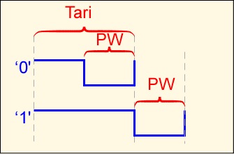
The reader symbols are distinct from those introduced previously but are fairly straightforward. A binary '0' is a short high level pulse followed by low pulse of equal length; a binary '1' is a longer high pulse followed by the same low pulse width. This symbol set provides a high average RF power delivered to the tag. The length of a binary '0' is defined as Tari, and is used as a reference for several other times in the standard. The data rate can vary from 27 to 128 Kbps (Tari from 25 to 6.5 microseconds); the most significant bit of the most significant word is always sent first. ![]() Communication between the tag and reader is packetized, conceptually similar to class 1 Gen I, but the packet details are quite different from the earlier standard. 
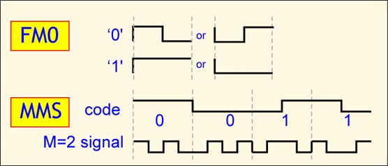
Two distinct sets of tag symbols are used. The basic approach is FM0: a binary '0' has a transition in the middle of a symbol, whereas a binary '1' does not. However, a second option is provided, Miller-modulated subcarrier (MMS). The FM0 signal is multiplied by a square wave with either 2, 4, or 8 periods for each FM0 symbol. It is important to note that, although in the figure below we show the FM0 symbol time as constant so you can see how the transmitted signal is related to the FM0 signal, in fact it is the time between transitions, or equivalently the link frequency, that is held constant. As a consequence, the data rate for a fixed link frequency is reduced by the MMS multiplier. If we set a link frequency of 100 KHz, FM0 provides a data rate of 100 Kbps, but MMS with a multiplier of M=4 only provides 25 Kbps. |

| It seems contradictory to intentionally reduce the data rate,
but MMS offers some advantages over FM0. In spectral terms, the
energy in an MMS signal is concentrated away from the carrier (roughly
by the link frequency), making it easier to detect in the presence of
phase noise and possible interference from other readers. In the
time domain, interpretation of an FM0 symbol depends on a single edge,
whereas an MMS symbol provides a number of edges to locate, reducing
the likelihood of a bit error. Inventory operations are based on slotted Aloha collision resolution. Unlike class 1 and class 0, no attempt is made to use the tag ID binary tree. Instead, the reader issues a QUERY command, and each tag effectively rolls a many-sided die, where the number of sides is set by the reader. A tag that rolls a 0 replies immediately; all tags that roll other numbers record those numbers in a counter and say nothing. The reader, after either receiving a reply or no response, can issue a QUERY REP command, causing all the tags to decrement their counters by 1; any tag reaching a counter value of 0 responds. If the number of sides is chosen properly, one and only one tag will respond to most of the QUERY REP commands. A tag replies by sending a 16-bit random number RN16. If the reader hears the random number it echoes that number as an acknowledgement, causing the tag to send its electronic product code and error check, along with some protocol control bits (PC). The PC bits provide the length of the EPC stored in the tag, as well as some information pertaining to the numbering system and optionally the type of object to which the tag is attached (the application family identifier (AFI)). The reader can then send commands specific to that tag, or continue to inventory other tags. |

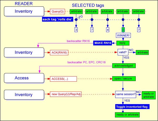
| The use of a random number as a handle
is an important feature of the Gen 2 protocol. This allows the
reader to define a unique session with a particular tag even if that
tag has not been identified, or does not have a unique EPC (e.g. if it
has just been received from the factor with its EPC initialized to all
0's). A Gen II reader can count tags in the field even if all the
tags have the same EPC. It can write to a single tag even if that
tag has not yet been given a unique identifier. Furthermore, the
sequence of exchanging a valid RN16 followed by transmission of the EPC
makes it less likely that the reader will see a ghost or phantom tag where none is present.
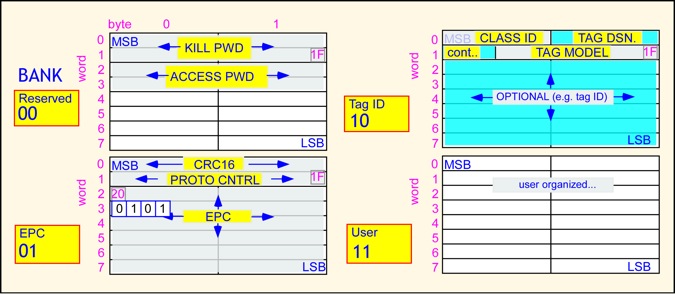
 Unlike the class 0 situation, the Gen 2 standard specifies the tag's memory organization. Memory is organized in 4 banks, organized into 32-bit words. Bank 00 is reserved for passwords for the lock and kill functions. Block 1 contains the protocol control bits, the error check, and the unique identifier, normally the EPC. Block 2 contains information about the tag, possibly including a unique tag identifier distinct from the EPC (that is, a number identifying the tag itself and not the object to which it is attached). Block 3 is user memory and may be organized in any fashion. A SELECT command, that works somewhat like the class 1 filter command, is available to choose tags which are to participate in a given inventory session. |

| If you'd like to get more familiar with the workings of
the protocol, a simple tag emulator and control panel implemented in
Python are available here. The emulator makes it possible to watch an example exchange between a reader and a tag. The ISO 18000 suite describes a series of passive tag standards. 18000-6A and 18000-6B are distinct UHF tag protocols. A few aspects of the standards are common, but the modulations, symbol sets, and command sets and mostly incompatible. At the time of this writing (2007) it appears that 18000-6C will become the most common worldwide standard for UHF passive tags in supply chain applications. The EPCglobal standards are specifically designed for supply chain applications. There are a number of other RFID protocols applicable to UHF operation, as well as numerous standards for LF and HF tags and readers. |
![]() www.enigmatic-consulting.com |
||
![]() |
![]() |
![]() |