A World Without Time:
Long wavelengths, short structures
Daniel M. Dobkin
revised December 2012
Solenoids and Vector Potentials:What you Didn't Know You Knew
Everybody who has taken a course in electromagnetism knows that the voltage induced in a loop is the integral over the contained surface of the time derivative of the magnetic field. This is Faraday's law and was known when Maxwell was a student.
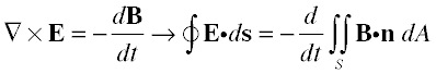
So if we apply this rule to a solenoid we get:
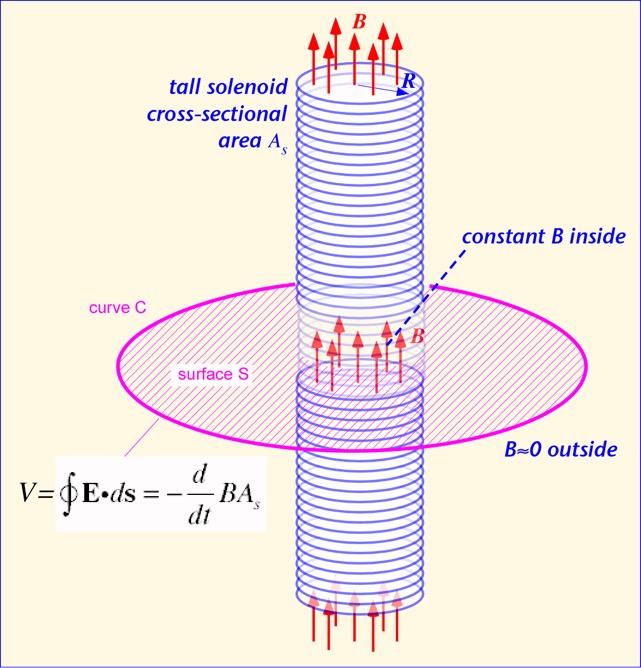
where B is the (roughly constant) magnetic field inside the solenoid and A the cross-sectional area of the solenoid. If the current in the solenoid is changed (slowly, so that the reactance of the solenoid is not a problem), a voltage is induced in an external coil following curve C. This is all uncontroversial, of course. But here's the interesting part: where does the voltage come from? The magnetic field we are integrating over is a couple of solenoid diameters away from the electrons in the outer coil; they have no way of knowing that it is there. Unless we wish to invoke action at a distance, which is usually avoided in modern field theory, we need to have a local quantity that affects the electron motion in the external coil.
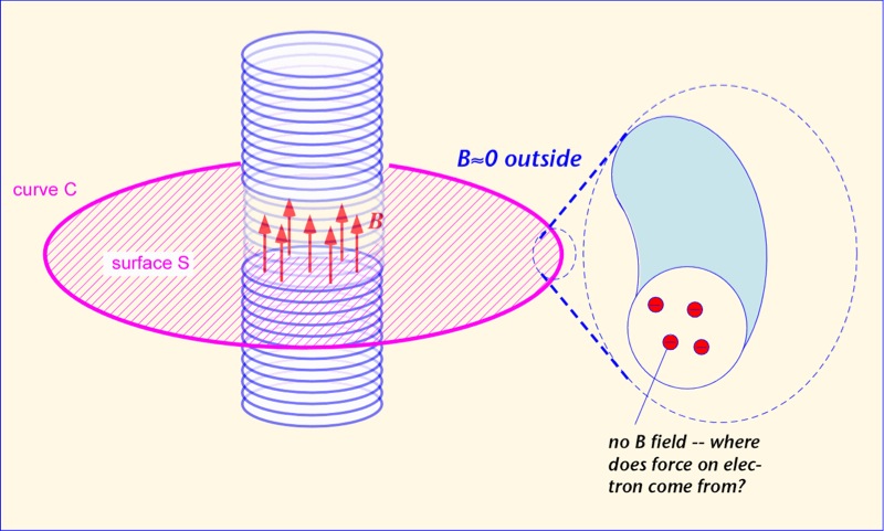
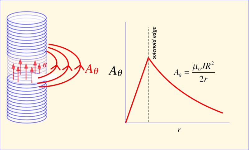
The answer, of course, is that the voltage is the result not of the magnetic field, but of the vector potential A. Outside the solenoid, the vector potential has only an azimuthal constituent, and falls in magnitude as the inverse of the distance. It is easy to verify that the function (1/r) has no curl away from r=0, so B is zero -- but A is not! It's also easy to see that the integral of (1/r) around a circular arc of radius r is constant -- (1/r) * r = 1 -- irrespective of the radius; that is, the integral of the vector potential around the loop is independent of the radius of the loop, so long as it is outside the solenoid, just as predicted by Faraday's law. It is the vector potential that pushes the electrons in the wire around, even in locations where the magnetic field vanishes. There is no need to calculate the magnetic field at all; just find A at the location of the loop, and take its time derivative in the direction of the loop of wire.
Note that, although finding the exact value of the vector potential might be a bit subtle, the relationship of forces and sources is very simple. The vector potential arises from the current on the solenoid and goes in the direction the current goes. The resulting electric field arises from the time derivative of the vector potential, and points in the same direction (and thus along the outer loop of wire). There are no cross-products or curls to take. One electron acts on another, and that's all you need to know.
Like Poe's Purloined Letter, A has been hiding in plain sight. Now that our eyes are opened, let's see where we can apply this new viewpoint to familiar problems.
A Straight Wire
"Surprisingly, it is not easy to find an expression for the inductance of a straight piece of wire, and it is far more difficult to find out how that expression was obtained".
--Prof. Tim Healy, University of Santa Clara
http://www.ee.scu.edu/eefac/healy/indwire.html
While Professor Healy is a very nice fellow, I think you'll agree in a moment that he's wrong, not because he's dumb (he certainly is not) but because he is using the wrong tool for the job. In his world, here's what you have to do to answer this question:
- Set up the geometry of a point at some distance from a straight line.
- Write dH from Biot Savart at that point. Let the current equal one for simplicity.
- Find the total H due to all of the current in the line by integrating over the line.
- Set B = μ H.
- Find the magnetic flux phi in a differential area which is parallel to the wire by integrating B over this area which is a fixed distance from the wire.
- Find the total flux phi over all of the area from the edge of the wire to infinity by integrating over the distance from the wire to infinity.
- Since the current was set equal to one, the total flux equals the inductance.
We'll do something much simpler. A comes from current I. We integrate the source equation over the (constant) current to get A (which is in the z-direction if the wire is along the z-axis -- no cross-products!). We can get a pretty danged good guess at the inductance by simply multiplying -dA/dt by the length of the wire, but for the picky folks we'll go farther and integrate the expression over the wire length. Everything happens along the axis of the wire. We don't care what goes on at infinite distance, and don't need to find the flux. Enough talk, let's see how it's done.
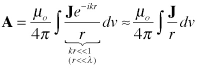
A great simplification of the source integral is obtained when the wire is very short compared to a wavelength (which is the only condition where it makes sense to talk about the wire as a lumped inductance in any case). When this is true, we can ignore the phase change from currents at different parts of the wire, or equivalently treat everything as happening at the same time. The source equation for the vector potential becomes:
To write out the integral we need to decide on a coordinate system and names for the dimensions of the wire. These are shown below. We'll assume the wire is along the z axis and place z=0 at the center of the wire. In these terms, the approximation above is valid when the wire length L is much smaller than the wavelength at the frequency of interest (which is, of course, c/f where c is the speed of light and f the frequency). Though we won't prove it here, for reasonably thick wires and high frequencies, the current is mostly at the surface of the wire, so all the current elements are the same distance from the wire axis. As long as we take the integral along the axis of the wire, we don't have to worry about the current density: we can just integrate over the perimeter of the wire to find the total current at each location z.
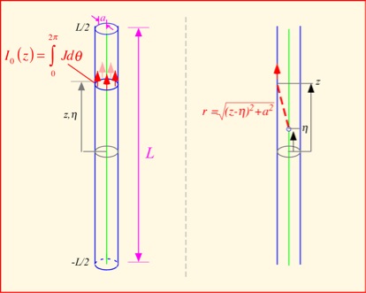
The simplest approach is to assume the current is constant along the wire. The vector potential is always in the direction of the current, so there is only a z component to worry about. The distance from a specific location on the axis to a location on the surface of the wire is the square root of the squared radius of the wire plus the difference in height between that of the surface location and the point on the axis. In mathematical terms:
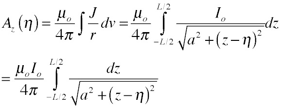
By remarkable happenstance, the last integral on the right is one of the integrals we reviewed in our discussion of useful tools. (Vonnegut would have said they're in the same kvass.) The result is simplest at the center of the wire:
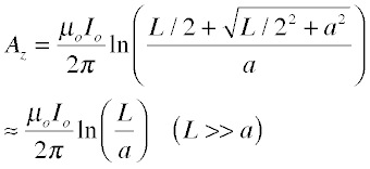
Depending on how accurate we want to be, we can quit now or do a bit more work. Because A is a logarithmic function and thus varies rather slowly along the wire, a quite reasonable approximation to the voltage is obtained by simply multiplying the potential in the middle by the length of the wire and taking the time derivative (which just multiplies the result by iω). Since voltage V = iω(inductance), we divide by the current and the angular frequency to obtain the inductance (to avoid confusion with the wire length we'll use the Greek letter for inductance):
So we got a reasonably good answer with one finite integral. Furthermore, the intuitive meaning of the answer is straightforward -- the inductance is proportional to the wire length and to a term that expresses how close the currents are to the center of the wire -- and it's easy to modify the approximation for shorter wires (where a is not negligible): we just use the radical expression instead of approximating it by L.
A plot of Az along the length of the wire (for a ratio of L/a=100) is shown below. It's easy to see that the potential is almost constant along the wire except very near the ends (where we really ought to be taking account of currents flowing on whatever connects to the wire). As long as the wire length is large compared to the radius, we have likely made only a modest error by our single-point integration.
If we want to be more accurate, we need to integrate the full expression for Az over the length of the wire. Except very near the ends we can expand the radicals to obtain a simplified expression, reasonably easy to integrate. It's substantially more work than the simple way:
That's a lot of labor for a tiny improvement! For reasonably large values of (L/a) the single-point integration is quite sufficient. When we use the right approach simple questions are simply answered.
Inductance of a Circular Loop of Wire
It's a bit more complicated to apply our methods to a loop, simply because the relationship between the location along the loop and the distance to a test point is more complex. A complete analytic solution requires hypergeometric functions (raise your hand if you've never heard of them -- you'll be in good company). In today's world I would argue that expressions in terms of sufficiently obscure functions are not particularly better than numerical integration. We want something we can work with.
We can get a respectably accurate estimate using a very simple approach. We approximate a circular loop with an "equivalent" square inductor, like this:
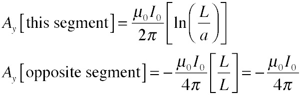
Now we exploit our results for the straight wire. We choose a test point in the center of one of the segments and find the vector potential there. Remember that the vector potential always points in the direction of the current, so if e.g. our test point is on a vertical segment, the two horizontal segments are perpendicular to the wire near the test point and thus make no contribution to A along the wire there, so we can ignore them entirely. The segment we are on can be treated in exactly the fashion we used above, since it is a length of straight wire. The opposite vertical segment can be treated as if it were all the same distance away (L), so the integration just becomes multiplication by the length L; this contribution gets a negative sign because the current is going in the opposite direction there. So we get:
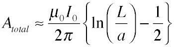
The total potential is the sum of these two terms:
We can find the voltage around the coil if we use the same simplifying assumption as before, that is, that A is nearly constant along the wire so integration just becomes multiplication by the perimeter, 4L. Taking the time derivative of the potential to get the electric field brings down a factor of iω, so we get:
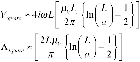
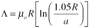
Now, what is the relationship between the length of the equivalent coil Leff and the radius of the original circular coil R? A plausible guess is to require that the perimeters of the two structures are equal: 4L = 2πR. Plugging in we get and expression for the inductance of a loop:
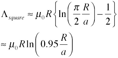
This estimate is quite accurate as long as the ratio R/a >> 1, and much more convenient to use than hypergeometric functions or elliptic integrals. Furthermore, it's apparent that we can partition the inductance of this structure (and plausibly of any loop) into two rather distinct parts: a portion from the wire nearby that looks almost like a straight wire contribution, and a portion from the distant "return" part of the loop that depends only on geometry and not on the dimensions of the wire.
One can go much farther than this, while still expressing all the results in terms of familiar functions, by integrating the potential for the round coil, using a quadratic approximation for the cosine; the procedure is straightforward but laborious, and produces after substantial algebra a slightly different (and slightly more accurate) result:
It's a lot of trouble to go through for not much numerical benefit (though in this case we don't need to pull a guess for an equivalent size of the square coil out of the air, which is admittedly cheating). Once again, we find that a good approximation to the full answer can be obtained from a very simple procedure, which also shows explicitly the contributions to the inductance from the radius of the wire and from its overall shape.
Simpler than B?
Hopefully you'll agree that for some common geometries, we really don't need to care about the curl of the potential when we can use the potential itself. In the next section we'll look at the simplest case in which time and wavelength are fundamental, the transmission line.